
Perfect Binder PB-503
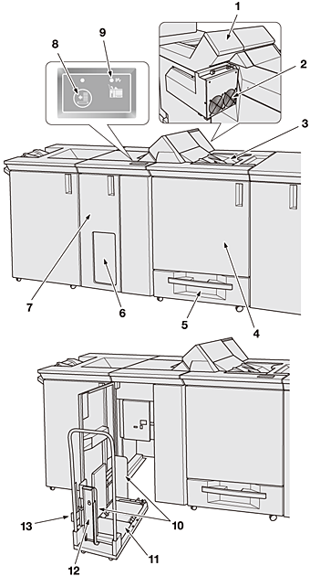
External view of Perfect Binder PB-503
No. | Name | Description |
|---|---|---|
1 | Glue hopper cover | Opens for supply of glue pellets. |
2 | Exhaust fan | Exhausts air from Perfect Binder PB-503. |
3 | Secondary (sub) tray | Holds sets output being processed by Perfect Binder PB-503. |
4 | Perfect binder tray front door | Opens to allow removal of paper jam and waste trimmings. Inside the Perfect binder front door, the glue tank unit is installed at the back. |
5 | Cover Tray | Holds cover paper for perfect binding. |
6 | Perfect binder tray window | Allows you to check the sets output to the perfect binder tray. If the sets are piled on the right side of the perfect binder tray, press the feeding button to feed them to the carriage. |
7 | Perfect binder tray front door | Opens to take out the bound sets from the tray. |
8 | Feeding button | Feeds bound sets into the carriage. |
9 | Paper jam indicator | Lights when a paper jam occurs in conveying sheets output from the finishing section of Perfect Binder PB-503. |
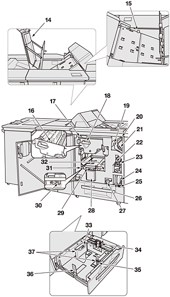
Internal view of perfect binder tray front door
No. | Name | Description |
|---|---|---|
10 | Book holding plate | Aligned to output books to prevent them from collapsing during portage. |
11 | Carriage | Carries perfect-bound books out from Perfect Binder PB-503. |
12 | Book stopper | Inserted to an appropriate stopper positioning hole to prevent output books from collapsing during portage. |
13 | Book holding plate lever | Moved to align the book holding plate to output books. |
Conveyance section
No. | Name | Description |
|---|---|---|
14 | Conveyance section cover | Opens to allow removal of paper jam when paper jam indicator lights. |
15 | Knob [PB14] | Turned counterclockwise to ease removal of paper jam. |
Internal view of perfect binder front door
No. | Name | Description |
|---|---|---|
16 | Body set release knob in clamp unit | Turned clockwise to take out the body set fixed in the clamp unit. |
17 | Knob [PB2] | Turned to feed the body set to the clamp unit for removal of paper jam. |
18 | Lever [PB7] | Pushed downward to withdraw the clamp unit for removal of body set jammed in the clamp unit. |
19 | Knob [PB6] | Turned to feed the jammed paper into the secondary (sub) tray. |
20 | Lever [PB3] | Opens downward for removal of jammed body set. |
21 | Lever [PB1] | Opens upward for removal of jammed body set. |
22 | Lever [PB12] | Opens upward for removal of jammed body set. |
23 | Lever [PB4] | Opens leftward to allow removal of jammed cover paper. |
24 | Lever [PB5] | Opens leftward with the trim scrap box drawn out for removal of jammed cover paper. |
25 | Knob [PB13] | Turned clockwise to ease removal of jammed cover paper. |
26 | Trim scrap box | Withdrawn for removal of waste trimmings. |
27 | Knob [PB11] | Turned upward to let the binding unit down for removal of paper jam. |
28 | Jam position display | Indicates the position of paper jam by LED lamps. |
29 | Knob [PB8] | Turned clockwise for removal of cover paper from the binding unit when paper jams. |
30 | Binding unit release knob | Turned downward for removal of cover paper from the binding unit in the top position. |
31 | Knob [PB9] | Turned clockwise to release the cover fixing plate for removal of paper jam. |
32 | Knob [PB10] | Turned counterclockwise to release the cover fixing plate for removal of paper jam. |
Internal view of cover tray
No. | Name | Description |
|---|---|---|
33 | Air nozzle | Blows air to avoid feeding multiple sheets of cover paper at a time. |
34 | Feed roller | Feeds cover paper sheet by sheet to Perfect Binder PB-503. |
35 | Lock release knob | Pushed backward to release the lock in order to move guide plates. |
36 | Rear stopper | Aligned to the rear edge of loaded paper. |
37 | Guide plates | Aligned to the edges of loaded paper. |