


Name and Function of Each Component

NOTICE
- For details about the Image Controller, refer to Types of Image Controller.
No. | Name | Description |
|---|---|---|
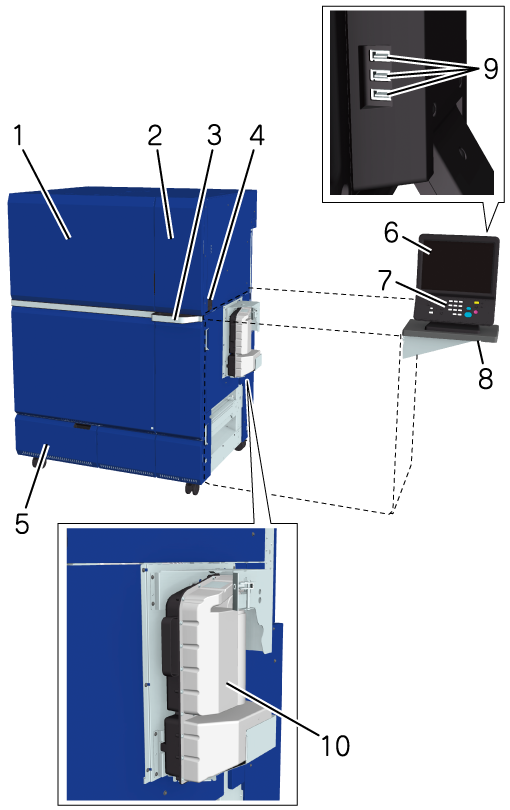
1 | Left side door | Open when clearing a paper jam or when turning Main power switch ON/OFF. |
2 | Toner supply door | Open when replacing Toner bottle. |
3 | Toner supply door handle | Used when opening Toner supply door. |
4 | Sub power switch | Turns the machine power ON/OFF. |
5 | Waste toner box replacement door | Open when replacing Waste toner box. |
6 | Touch panel | Displays the screens such as the [MACHINE] screen, and set up operations. Also, displays the operation method and method for handing problems. |
7 | Control panel | Press when operating and setting up. |
8 | Working Table WT-518 (optional) | Mount the Control panel. |
9 | USB port (USB 2.0 Type A e 3) | Used when attaching the following items.
etc. USB port (USB 2.0 Type A e 3) supports low power devices only. Please provide an external supply of power for devices that require a large amount of power. |
10 | Cyclone Box | Reduces toner scattering in the machine. Access the Cyclone Box from within the paper feeder unit or the Intelligent Media Sensor IM-104. |
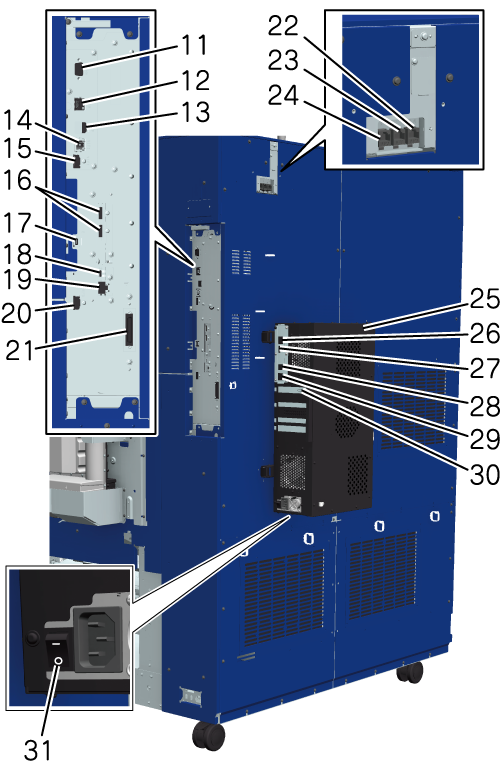
11 | Serial port (RS-232C) | Port for customer engineer (CE) only. |
12 | Network port (10BASE-T, 100BASE-TX, 1000BASE-T) | Connects an Ethernet cable to operate the system and uses as a network scanner. |
13 | USB port (USB 3.0/2.0 Type A e 1) | Used when attaching the following items.
USB port (USB 3.0/2.0 Type A e 1) supports low power devices only. Please provide an external supply of power for devices that require a large amount of power. |
14 | Image Controller connection port | Used when mounting all the Image Controller. |
15 | Auto Inspection Unit connection port | Used when mounting the Auto Inspection Unit AI-101. |
16 | Video Interface Kit connection port* | Connect the cable of Video Interface Kit VI-514 or Video Interface Kit VI-515. Used when mounting the Auto Inspection Unit AI-101 or connecting to the Image Controller manufactured by Fiery or Kodak. * Video Interface Kit VI-515 (optional) is required to connect the Image Controller manufactured by Fiery or Kodak and the machine using a cable. |
17 | Intelligent media sensor connection port | Used when mounting the Intelligent Media Sensor IM-105. |
18 | Auto Inspection Unit connection port* | Used when mounting the Auto Inspection Unit AI-101. |
19 | Service port* | Port for customer engineer (CE) only. |
20 | Image Controller connection port | Used when mounting the Image Controller. |
21 | Control Panel connection port | Connect to the Control panel. |
22 | Unusable port | This port is not available. |
23 | Network port | Used when mounting the Intelligent Quality Optimizer IQ-601. |
24 | Network port | Used when mounting the Intelligent Media Sensor IM-104. |
25 | Image Controller IC-614 | This system can be used as a printing system. |
26 | Machine Connection Port | Connect to the machine. |
27 | Auto Inspection Unit connection port | Used when mounting the Auto Inspection Unit AI-101. |
28 | Service port | Port for customer engineer (CE) only. |
29 | Network port (10Base-T, 100Base-TX, 1000Base-T) | Connects an Ethernet cable to operate the Image Controller, and uses as a network printer. |
30 | Machine Connection Port | Connect to the machine. |
31 | Power switch | Turns the Image Controller power ON/OFF. |
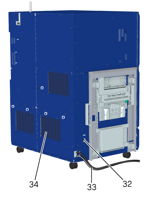
32 | Heater switch | Switch Paper Feeder Unit PF-712 / Paper Feeder Unit PF-713 / Paper Feeder Unit PF-812 heater ON/OFF. |
33 | Power cord | Supplies power to machine. |
34 | Ozone filter | Recovers ozone generated inside the machine. |
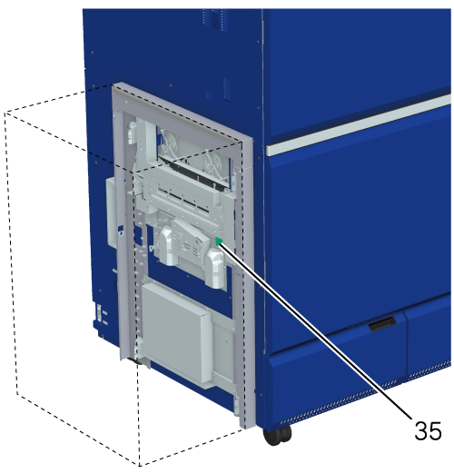
35 | Lock release lever | When clearing a paper jam, push the lever to the back, open the guide downward, then remove the paper. Access Lock release lever from within the options on the left. |
*: Connection port used when Video Interface Kit VI-514 is mounted.
 in the upper-right of a page, it turns into
  and is registered as a bookmark.