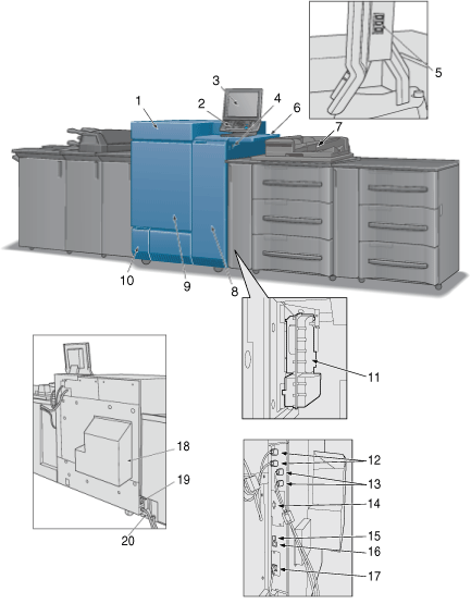
External Machine


No. | Name | Description |
|---|---|---|
1 | Toner supply door | Opens to allow toner supply. |
2 | Control panel | Used for various settings and machine operations. |
3 | Touch panel | Displays screens such as the MACHINE screen to allow various settings and machine operations. Also, operation or troubleshooting procedures can be provided. |
4 | Sub power switch | Turns machine power on/off when pressed. |
5 | Service port (USB 2.0 Type A 3) | Used to connect devices such as an external storage medium (USB flash drive, USB-HDD), keyboard and mouse. This port is available for low-power devices only. Please provide an external supply of power for devices that require a large amount of power. The length of a total cable which connects USB devices should be shorter than 3 m. |
6 | Working Table WT-512 (option) | Provides a convenient workspace for documents before and after copying. |
7 | Dual Scan Document Feeder (ADF) | Mounted on Paper Feed Unit PF-711. Automatically feeds multiple originals on a sheet basis to scan data. |
8 | Right side door | Opens rightward for removal of paper jam. |
9 | Left side door | Opens to allow removal of paper jam or to turn on/off the main power switch. |
10 | Waste toner box replacement door | Opens to allow replacement of the waste toner box. |
11 | Cyclone Box | Prevents toner from scattering in the machine. The cyclone box can be accessed from the inside of the paper feeder unit. |
12 | Paper feeder unit connection port | Used to connect Paper Feed Unit PF-711 by cable. It is not provided to the machine which does not connect Paper Feed Unit PF-711. |
13 | Integrated Color Care Unit Connection Port | Used to connect Integrated Color Care Unit IQ-501 by cable. |
14 | Video Interface Kit Connection Port | Used to mount Video Interface Kit VI-509 (optional). *Video Interface Kit VI-509 (optional) is required to connect Image Controller IC-313, Image Controller IC-314 or Image Controller IC-315 to this machine by cable. |
15 | Service port (USB 3.0 Type A 1) | Used to connect Authentication Unit AU-201S. |
16 | Service port (USB 2.0 Type B 1) | Connect this machine to the computer using a USB cable in order to use it as a local printer. |
17 | Network port (10Base-T, 100Base-TX, 1000Base-T) | Connected with an image controller or Ethernet cable to use the machine as a network printer or scanner. |
18 | Dust proof filter | Attached for cooling fan in order to keep out dust. |
19 | Heater switch | Turns on/off the heater of the machine. |
20 | Power cord | Supplies the main body with electric power. |
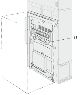
21 | Lock release lever | Pressed to the back to open downward for removal of paper jam. The Lock release lever can be reached from the left side optional equipment. |