
Registering a Profile Set with Color Centro
Start Color Centro, and create and save a profile set.
Start Color Centro and log in to the machine. ( Refer to Start Color Centro.)
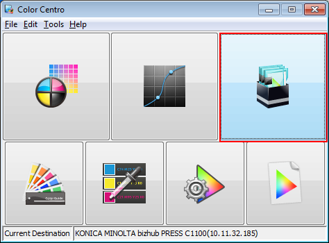
The Color Centro launcher screen is displayed.
Click [Color Configuration] on the launcher screen.
The [Color Configuration Management] screen is displayed.
Click [Execute].
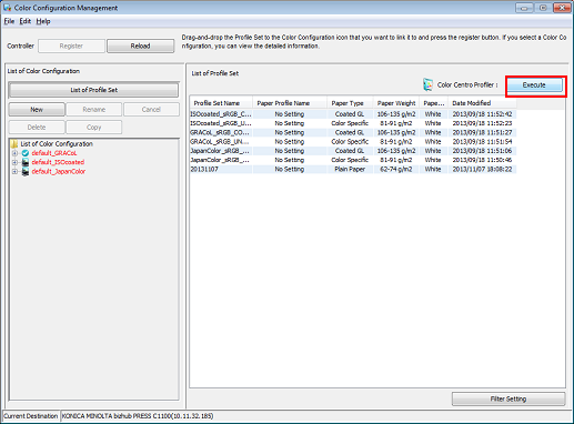
[Color Centro Profiler] starts.
Click [Create new Profile Set]
 .
.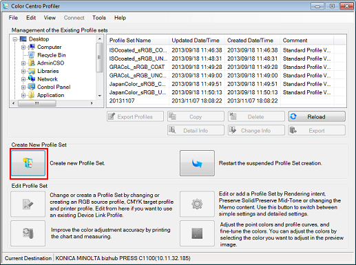
The wizard for creating a new profile set starts.
On the [Confirmation of procedure] screen, click [Next].
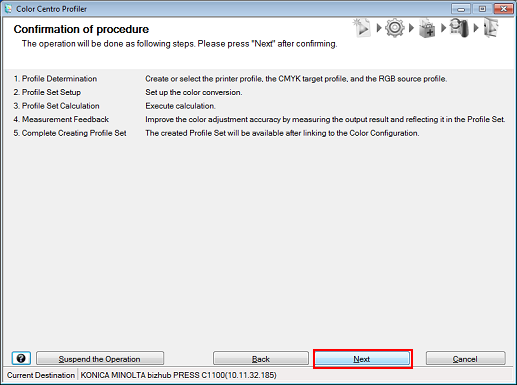
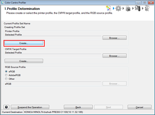
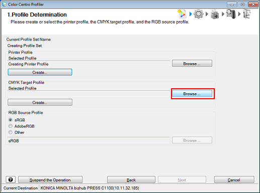
[1. Profile Determination] screen is displayed.
Click [Create] for the printer profile to be used.
Here, the procedure for creating a new printer profile is explained.
To select an existing printer profile, click [Browse] and select a profile.
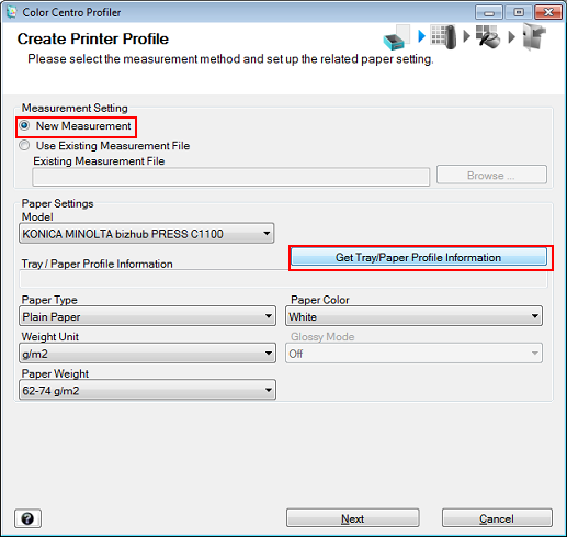
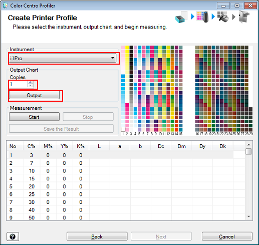
The [Create Printer Profile] screen is displayed.
Select [New Measurement] under [Measurement Setting] and click [Get Tray/Paper Profile Information].
To make a new measurement with the instrument, select [New Measurement].
Example: Click [Get Tray/Paper Profile Information] so as to use the paper setting for Tray 3 (Coated GL: (A3) 128 g/m2 / 33 lb Bond).
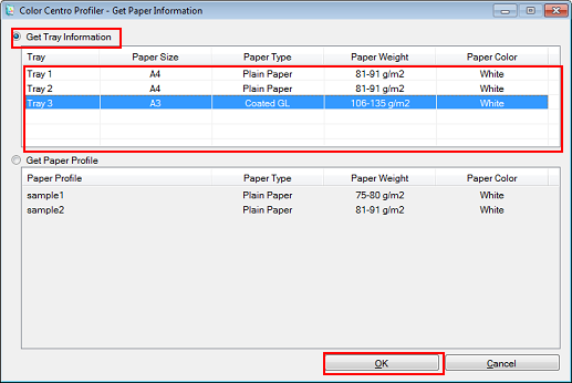
Select [Get Tray Information] on the [Get Paper Information] screen. After selecting the tray in which the papers are loaded, click [OK].
Example: Tray 3 is selected.
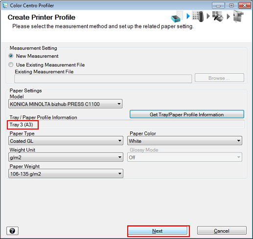
After checking that the selected tray and paper information are correctly displayed under [Tray/Paper Profile Information], click [Next].
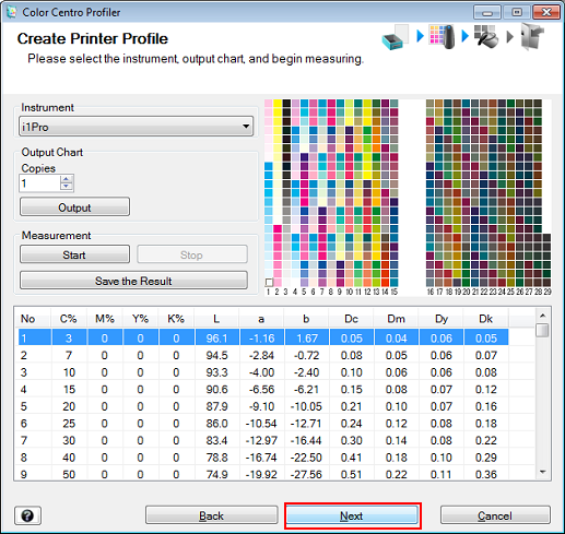
For [Instrument], select the instrument to be used. Set [Copies] and click [Output].
Print the color chart that is to be measured using the instrument.
Example: [i1Pro] is selected with 1 copy.
Item
Setting
[Instrument]
[i1Pro]
[Copies]
1
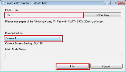
The [Output Chart] screen is displayed.
On the [Output Chart] screen, set the [Paper Tray] and [Screen Setting]. After setting, click [Print].
Example: Set the [Paper Tray] to [Tray 3], and the [Screen Setting] to [Screen 1] (default).
Item
Setting
[Paper Tray]
[Tray 3]
Click [Select Tray] and select a tray.
[Screen Setting]
[Screen 1] (default)
A test chart is printed.
Connect the instrument to the computer.
The device driver for the instrument must be installed on your computer beforehand. For details, refer to the instrument's manual.
Stack 10 sheets of blank paper whose type is the same as that of the paper where chart has been printed, and place the printed chart on top of it.
To eliminate the influence of the color of the table, place 10 sheets of paper of the same type as the chart underneath the chart to be measured.
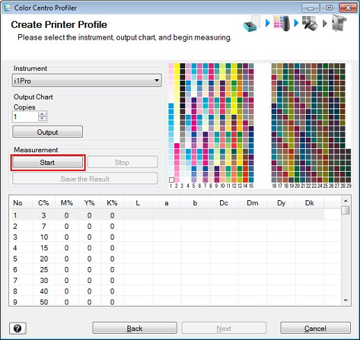
Click [Start].
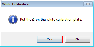
When the following message is displayed, place the instrument flat on the calibration dock and click [Yes].
When the following message is displayed, click [OK].
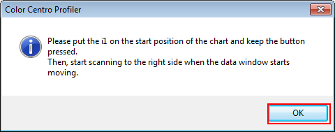
Press and hold the button on the instrument. When the bottom part of the screen starts scrolling, while holding the button, slide the instrument over the chart toward the right from the top left patch.
Measure the rest of the patch rows by sliding the instrument the same way.
After you finish the chart measurement, click [Next] on the [Create Printer Profile] screen.
When the chart measurement is completed, the measurement result is displayed at the bottom of the [Create Printer Profile] screen.
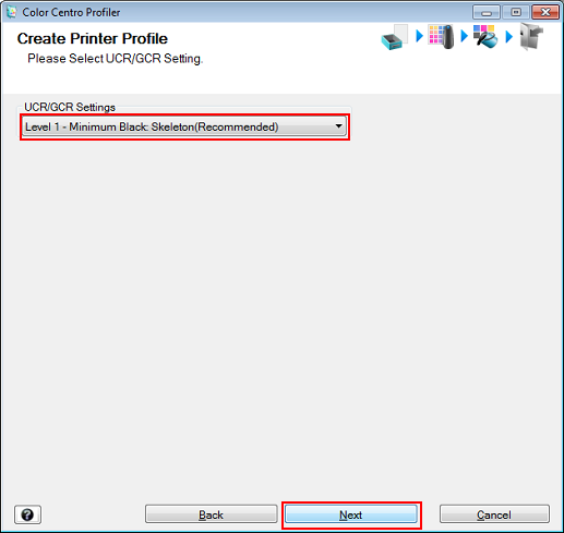
Check the [UCR/GCR Settings] and click [Next].
Example: [Level 1 - Minimum Black Skeleton (Recommended)] is used.
The message, [Calculating] is displayed, followed by the message, [Printer profile calculation complete] is displayed.
Click [Exit].
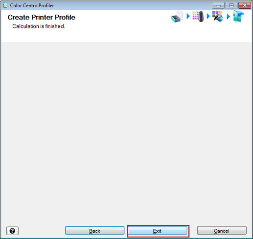
The created printer profile is saved.
Click [Browse] to select the CMYK target profile to be used.
Example: Click [Browse] to select an existing CMYK target profile.
The [Select CMYK Target Profile] screen is displayed.
Select a folder from the left side, and then select a CMYK target profile from the list on the right side. Click [OK].
Example: The bottommost controller folder in the tree to the left side is selected.
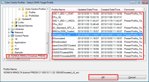
The selected CMYK target profile is set.
Select an RGB source profile. Click [Next].
Example: [AdobeRGB] is selected.
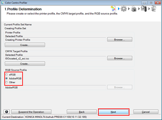
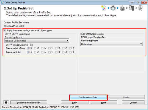
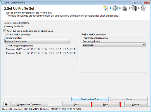
The [2. Set Up Profile Set] screen is displayed.
Set the color conversion (rendering) for each object. After setting, click [Confirmation Print] to check the result.
In this example, [Apply the same settings to the all object types] is selected. Selecting this option applies the same setting to image, graphics, and text (sample screen).
Item
Function
[Apply the same settings to the all object types]
Clearing allows you to use different rendering settings for image, graphics, and text.
[CMYK-CMYK Conversion]
[Rendering Intent]
[Relative Colorimetric]: Executes color conversion while regarding the paper color as pure white. The paper color parts are represented as colorlessness after color conversion.
[Absolute Colorimetric]: Executes color conversion while maintaining the measurement value of the paper color. The paper color parts are represented with the color near the actual paper color after color conversion.
* When you select [Absolute Colorimetric], [Preserve Mid-Tone] and [Preserve Solid] (except for K) cannot be set.
[Preserve Mid-Tone]
Reproduces colors composed of single colors using only those colors.
[Preserve Solid]
Reproduces solid colored parts with the same solid colors as before the color conversion.
[RGB-CMYK Conversion]
[Rendering Intent]
[Saturation]: Reproduces colors so that they maintain a similar level of brightness as before conversion.
[Perceptual]: Reproduces colors so that they are close to the colors before conversion.
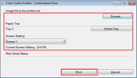
On the [Confirmation Print] screen, specify the image file to be printed, paper tray, and screen to be used. After setting, click [Print].
Example: Set the [Paper Tray] to [Tray 3], and the [Screen Setting] to [Screen 1] (default).
Item
Setting
[Image file to be printed out]
Click [Browse] and select the TIFF, PS, or PDF file to be printed.
Only one type, TIFF, PS, or PDF, can be printed.
[Paper Tray]
[Tray 3] (tray in which the relevant papers are loaded)
[Screen Setting]
[Screen 1] (default)
The selected file is printed.
After checking the print, change the settings on the [2. Set Up Profile Set] screen (Step 24) as necessary.
On the [2. Set Up Profile Set] screen (Step 24), click [Next].
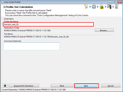
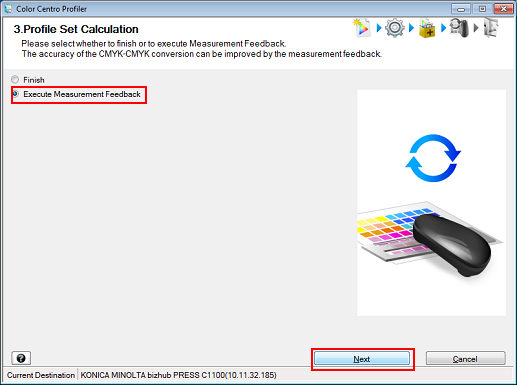
The [3. Profile Set Calculation] screen is displayed.
Enter a profile set name in the [Profile Set Name] field and click [Next].
Example: "Sample_coat_GL" is entered in [Profile Set Name].
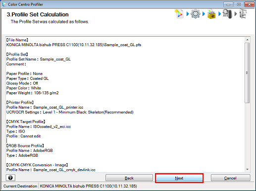
The message, [Registering] is displayed, followed by the message, [Profile set calculated using the following details] is displayed.
Check the profile set calculation and click [Next].
Select [Execute Measurement Feedback] and click [Next].
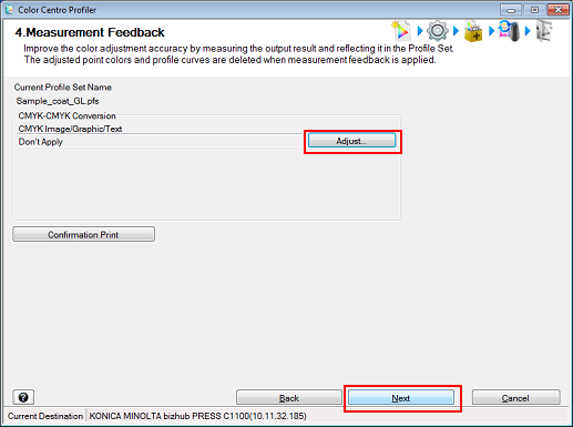
The [4. Measurement Feedback] screen is displayed.
Click [Adjust] to start measurement feedback. After the measurement is completed, click [Next].
Measurement feedback is an operation used to improve the accuracy of CMYK-CMYK device link profiles.
By following the instructions on the screen, execute measurement feedback for each CMYK object (image, text, and graphics) (Refer to Execute Measurement Feedback).
Click [Finish].
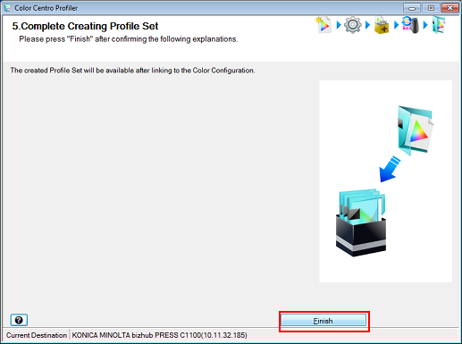
The created profile set is saved.
Proceed to register the profile set in color configuration by following the procedure in Register the Color Configuration.