
Checking the Name and Function of each Part in this Machine
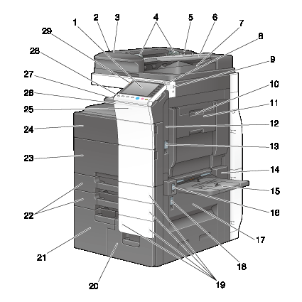
Front side
|
No. |
Name |
Description |
|---|---|---|
|
1 |
Control Panel |
Used to configure various settings in this machine. |
|
2 |
Left Cover Release Lever |
Used to open the Left Cover. |
|
3 |
Left Cover |
Open the Left Cover when clearing a paper jam. |
|
4 |
Lateral Guide |
Adjust this guide along the width of the original. |
|
5 |
Dual Scan Document Feeder |
Automatically feeds and scans originals by page. This unit scans a 2-sided original by only requiring the paper be fed into the machine once without reversing. This unit is referred to as ADF in the manual. |
|
6 |
Original Tray |
Load the original face up in this tray. |
|
7 |
Original Output Tray |
The scanned original is fed out onto this tray. |
|
8 |
Stylus Pen |
Used to select a menu on the Touch Panel, or enter characters. |
|
9 |
USB Port (Type A) USB2.0/1.1 |
Used to connect an external memory unit (USB memory unit) to this machine. |
|
10 |
Automatic Duplex Unit Release Lever |
Used to lock the Auto Duplex Unit. |
|
11 |
Auto Duplex Unit |
Used to reverse paper when performing 2-sided printing. |
|
12 |
Top Right Door |
Open this door to clear a paper jam. |
|
13 |
Top Right Door Release Lever |
Used to lock the Top Right Door. |
|
14 |
Bypass Tray Door |
Open this door when clearing a paper jam in the Bypass Tray. |
|
15 |
Bypass Tray |
Used to print data on irregularly size paper, thick paper, transparencies, postcards (4
Allows you to load up to 150 sheets of plain paper, 100 sheets of Thick 1, 80 sheets of
Thick 1+, 70 sheets of Thick 2, 60 sheets of Thick 3, 50 sheets of Thick 4, 20 sheets of transparency,
postcards (4 |
|
16 |
Bypass Tray Door Lever |
Used to lock the Bypass Tray Door. |
|
17 |
Bottom Right Door |
Open this door to clear a paper jam. |
|
18 |
Bottom Right Door Release Lever |
Used to lock the Bottom Right Door. |
|
19 |
Paper-Empty Indicator |
Flashes or lights up to indicate the remaining paper on the tray. For details, refer to Here. |
|
20 |
Tray 4 |
Allows you to load up to 1000 sheets of plain paper. Allows you to load up to 750 sheets of Thick 1, 500 sheets of Thick 1+, 450 sheets of
Thick 2, 400 sheets of Thick 3, 200 sheets of postcards (4 |
|
21 |
Tray3 |
Allows you to load up to 1500 sheets of plain paper. Allows you to load up to 1150 sheets of Thick 1, 800 sheets of Thick 1+, 700 sheets of
Thick 2, 600 sheets of Thick 3, and 200 sheets of postcards (4 |
|
22 |
Tray1, Tray2 |
Allows you to load up to 500 sheets. Allows you to load hold up to 400 sheets of Thick 1, 280 sheets of Thick 1+, 250 sheets of Thick 2, and 200 sheets of Thick 3. |
|
23 |
Lower Front Door |
Open this door to replace a Waste Toner Box or Imaging Unit, and to clean the Print Head Glass. |
|
24 |
Upper Front Door |
Open this door to replace a Toner Cartridge. |
|
25 |
Data Indicator |
Flashes or lights up to indicate the data receiving status on this machine. For details, refer to Here. |
|
26 |
Status Indicator |
Flashes white during printing. |
|
27 |
Output Tray |
Collects printed pages. |
|
28 |
Power key |
Press this key to switch to the Power Save mode. During the normal operation, the key lights up blue. During the power save mode, the key flashes blue or lights up orange. |
|
29 |
Warning Indicator |
Flashes or lights up to indicate that a problem has occurred in this machine. For details, refer to Here. |

Rear side
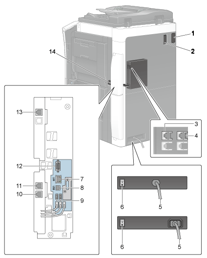
The illustration shows the unit with Heater, optional FAX Kit FK-511, FAX Kit FK-508, and Fax Mount Kit MK-728 installed.

-
The Heater is handled as an optional unit depending on sales areas.
-
FAX Kit FK-508 and Fax Mount Kit MK-728 can be used in North America.
|
No. |
Name |
Description |
|---|---|---|
|
1 |
Finisher Connector |
Connect the cable of the Finisher. |
|
2 |
Filter |
Used to collect toner powders inside the main unit. |
|
3 |
Telephone Jack 3 (FAX3) |
Used to connect a general telephone subscriber line. |
|
4 |
Telephone Jack 4 (FAX4) |
Used to connect a general telephone subscriber line. |
|
5 |
Power Cord |
Used to supply power to this machine. The shape of the Power Cord varies depending on the sales region. |
|
6 |
Heater Power Switch |
Used to turn Heater operations on or off. This function prevents paper from being affected by humidity when the power is turned on. |
|
7 |
Network Connector (10Base-T/100Base-TX/1000Base-T) |
Connect to this port when using this machine as a network printer or network scanner. |
|
8 |
USB Port (Type B) USB2.0/1.1 |
Connect to this port when using this machine as a USB-connected printer. |
|
9 |
USB Port (Type A) USB2.0/1.1 |
Used to connect Authentication Unit AU-102 or Authentication Unit AU-201. |
|
10 |
Jack for connecting a telephone (TEL PORT1) |
Used to connect a telephone cord. Connect the cord to this connector when using only one telephone line. |
|
11 |
Telephone Jack 1 (LINE PORT1) |
Used to connect a general telephone subscriber line. Connect the cord to this connector when using only one telephone line. |
|
12 |
RS-232C port |
Used to connect an IC card unit for JScribe. |
|
13 |
Telephone Jack 2 (LINE PORT2) |
Used to connect a general telephone subscriber line. |
|
14 |
Ozone Filter |
Used to collect ozone inside the main unit. |
Inside
|
No. |
Name |
Description |
|---|---|---|
|
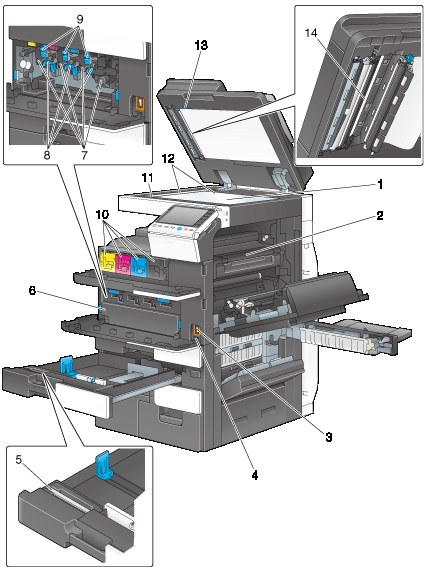
1 |
Original Glass |
Used to load the original. |
|
2 |
Fusing Unit |
Used to fuse toner to paper using heat and pressure. |
|
3 |
Main Power Switch |
Press this switch to turn the machine on or off. |
|
4 |
Total Counter |
Counts the total number of printed pages to date. |
|
5 |
Printhead Cleaner |
Used to clean the surface of the Print Head Glass when replacing the Imaging Unit. |
|
6 |
Waste Toner Box |
Used to collect used waste toners. |
|
7 |
Imaging Unit |
Used to create a print image. |
|
8 |
Charger Cleaner |
Used to clean the Electrostatic Charger when an image error occurs. |
|
9 |
Lock Release Tab |
Used to remove the Imaging Unit. |
|
10 |
Toner Cartridge |
This machine provides Toner Cartridge in four colors: cyan (C), magenta (M), yellow (Y), and black (K). A full-color image is created by combining the four toner colors. |
|
11 |
Slit Scan Glass (front) |
Used to scan an original image when using the ADF. |
|
12 |
Original Scale |
Load the original along this scale. This scale is also used to measure the size of the loaded original. |
|
13 |
Opening and Closing Guide |
Lever that locks the guide to scan the back side of an original. Open this guide when clearing a paper jam or cleaning the Slit Scan Glass (back). |
|
14 |
Slit Scan Glass (back) |
Used to scan the back side of an original when using the ADF. |